
STEREO FIELD DIY

*Kit contents (plus 5 small wood screws not pictured)

Start with the green I/O board by placing the 4 ¼” jacks into the same side of the board which has the large silver capacitors -- The opposite side as the 3.5mm jacks.

Check to make sure the 1/4” jacks are pushed in and flush with the PCB before flipping over in preparation of soldering each of the 4 legs.

Solder the 4 legs of each 1/4” jack while being careful not to melt the plastic on the 3.5mm jacks close by.

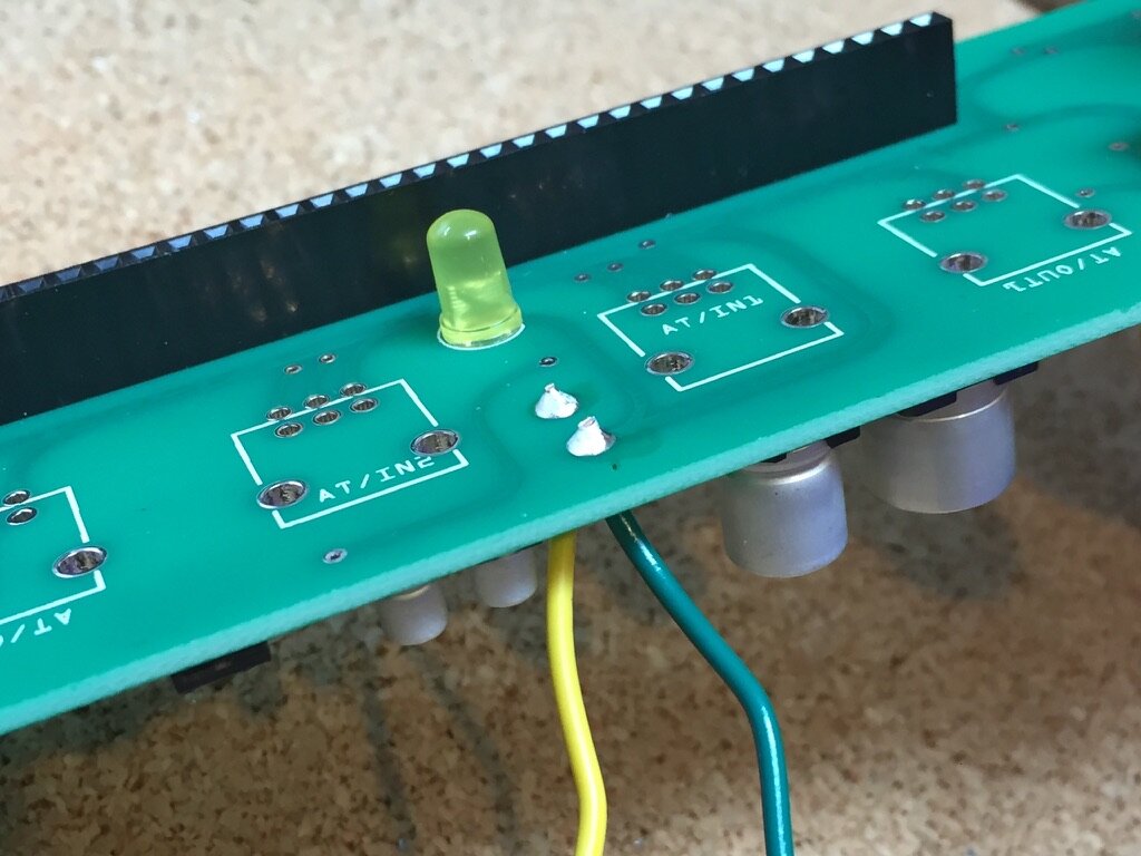
Flip the board over. Find the Yellow LED and place the legs into the PCB where it says LED. The longer of the two legs will insert into the square hole and double check that the slightly flattened side of the LED matches the flattened side of the board graphic.

Flip the board over to expose the two legs. Press the LED to be flush with the board and then bend the two legs outwards as shown above. This will ensure the LED doesn’t fall downwards while you are soldering it in place.

After soldering the LED use clippers to trim away the excess portion of the legs.

Locate the Yellow and Green wires. Use your wire strippers to expose about this much bear wire on each side.

Place one end of the Green wire in the hole closest to the edge of the board between the large and small silver capacitors. Now place the Yellow wire in the hole directly behind it.

While holding onto these wires (ensuring they remain in place) flip over the board and fold the wires over the edge as shown above. This folding action will keep them in place during soldering.

Now solder both wires in place.
Clip the excess exposed wire so they look similar to this.

Using pliers or your fingers, gently bend the opposite exposed ends of the wires in a hook shape.

Starting with the Green wire, hook the end through the center lug of the DC jack. It’s important to double check you are connecting to the correct lug in this step.

Now hook the Yellow wire to the shorter lug shown here below the center (green connection) lug. The longer solder lug will remain unconnected.

Flip the board with the 1/4” jacks on top as shown above and bend the wires to position the DC jack atop the closest 1/4” jack. This will act as your support for the soldering process.

Solder both wires to the DC jack. Again checking that the wires are connected to the correct lugs.

Using pliers or clippers, remove (break off or clip) the small tab from the potentiometers, this is important and will ensure that the assembly is flush.

Flip the board back over and place all 4 potentiometers taking caution not to fold any of the legs under in the process.

*Go slow with these next few steps to ensure no damage to the I/O board as well as the Pins in the large Pin Header. Read the next four steps before continuing on.
Holding the large Interface PCB in one hand and the I/O board in the other gently begin to insert the shafts of the potentiometers in the 4 center holes.

As the pots are inserted you will then gently align the black and gold pin header to ensure all 32 pins are going directly into their sockets. *Read next step before applying pressure here.

Double check that the 3.5mm jacks are also properly aligned before pressing the pin header together.

Press from the center point and work your way back and forth taking caution not to force or bend the board a lot. There will be a good deal of wiggling and pressing in this step to get the 3.5mm jacks to go in bit by bit will also getting the pin header to fully connect flush as pictured above. At times you make hear the 3.5mm jacks loudly pop through into their place (this is normal).

After double checking the pin head and board are fully set flip the assembly over to begin placing the 3.5mm jack Hex Nuts. Use your fingers at first to tighten all 8 a bit.

Using a socket driver to pliers, very carefully tighten all 8 of the Hex Nuts. In this step it is possible to scratch the surface of the interface. Go slowly and don’t apply very much downwards force.
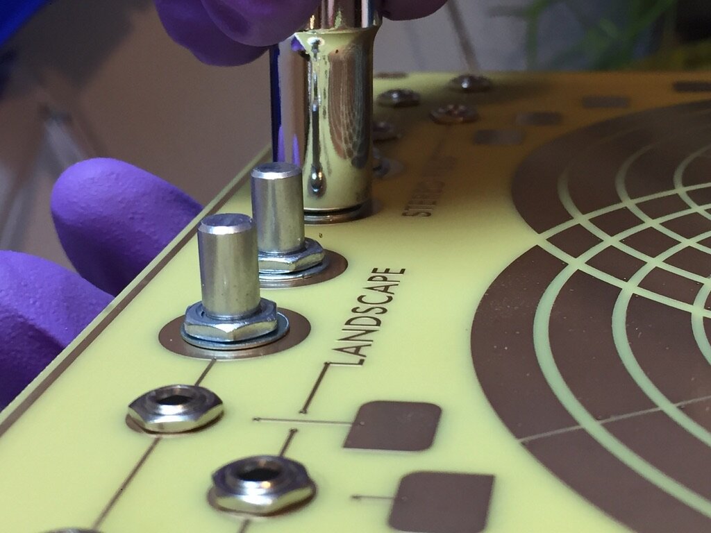
Pull each pot shaft upwards to expose the threading. Now place the washer and nut and tighten with your hands a bit. Next using a socket or pliers, gently tighten to avoid scratching the surface.

Flip the assembly over to check the pins of the pots are all equally flush to the PCB board. Only a very small portion of each pin will be exposed.
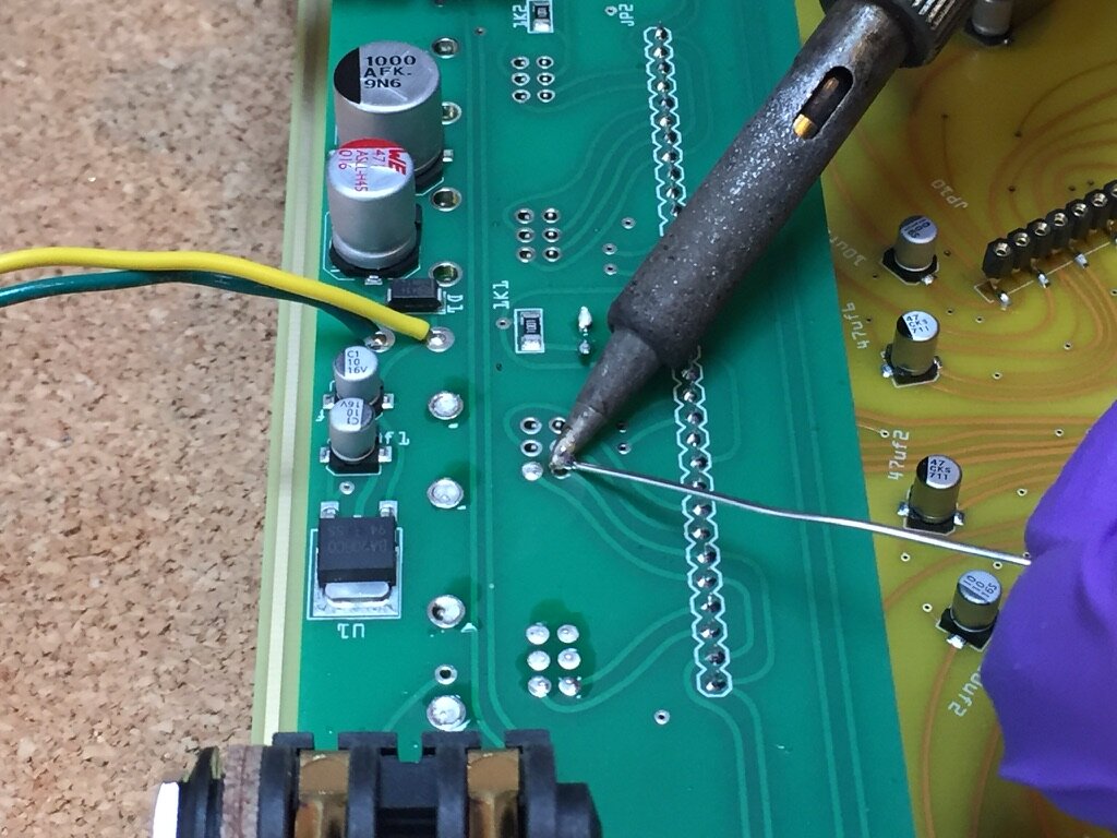
Apply solder to the large legs (2 per) and small legs (6 per) of all 4 pots.

Locate two LA3161 Op-amps and note where the diagonal edge is.
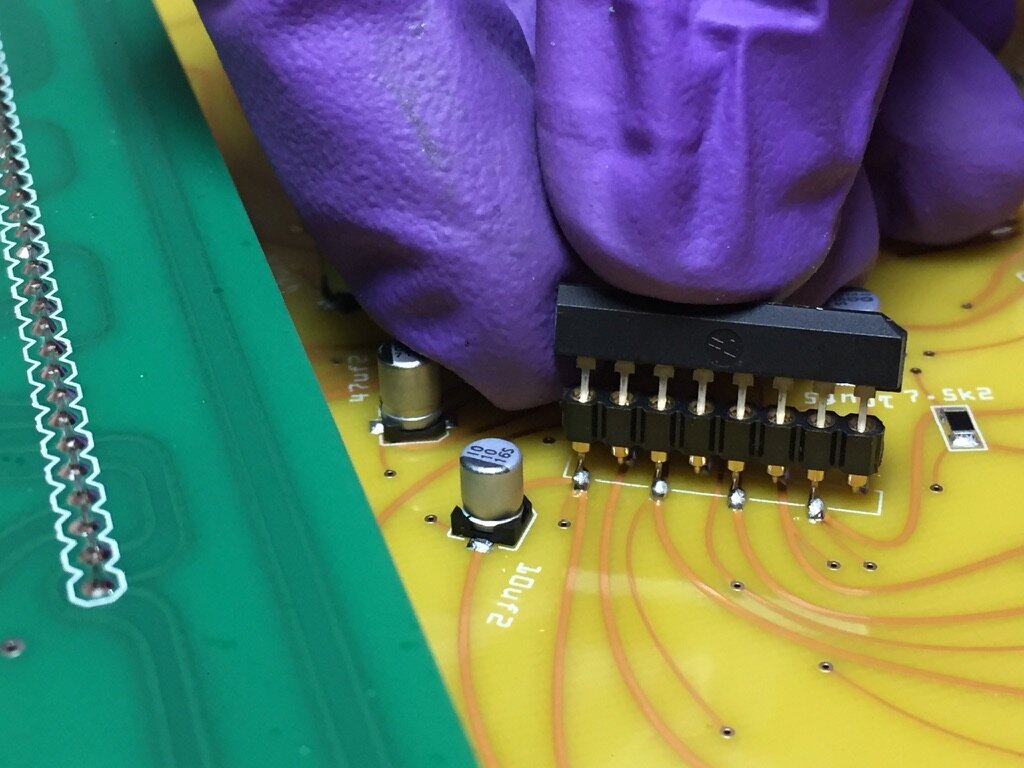
Insert each chip gently with the diagonal corner facing away from the green I/O board.

Double check both chips are inserted in this direction and nearly flush as pictured.

Flip over board and turn each potentiometer fully to the left.

Place each knob with a downwards 45 degree angle, lift up very slightly to make sure it’s not touching the nut below and then tighten into place.

Remove the 4 jack nuts from the 1/4” jacks and throw away one of the two spacer rings from each.

Remove the protective plastic fully from the aluminum case.

Important!: Place the pink foam included with your kit along the front edge of the case before proceeding to protect the underside components of the interface board. At no time should you slide the board along this edge because damage will occur and parts will be knocked off.

Place the board on top of the foam while attaching the DC jack into the center hole using the washer and nut. Hand tighten.

Very gently begin to tighten the DC jack nut while holding the backside with your other hand. The aluminum can be scratched very easily in this step so go slowly here and attempt to not make contact with the aluminum it self. See gap.

Gently tilt the PCB in place while never allowing the underside to touch the sharp front Aluminum case edge. The 4 1/4” jacks will slide into place. You may need to apply some wiggling and downwards pressure to fit the PCB but never press on the center (avoid bending) only press the edges.

Make sure the interface board is flush around all sides of the case. Tighten the 1/4” jack nuts and using a small screwdriver gently tighten the 4 wood screws into place, do not over tighten!

Apply Rubber Feet over the 4 screws on the underside of the unit. You’ve done it! To clean your Stereo Field interface, use rubbing alcohol with a soft cotton cloth.